Smps circuit diagram with explanation pdf Pormpuraaw
Computer Power Supply- Diagram and Operation AC to DC converter SMPS. It is almost related to the above discussed converter, but in the place of DC power supply, here we have used AC i/p. So, the mixture of the rectifier &filter, this block diagram is used for converting the AC to DC and the switching operation is done by using a power MOSFET amplifier.
Simple 12V 1A SMPS Circuit Homemade Circuit Projects
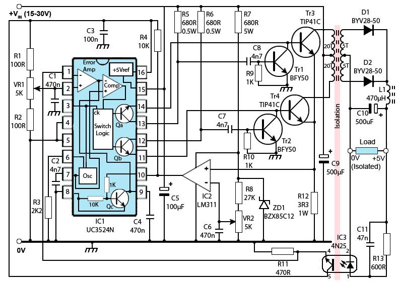
42 W 12 V 5 V SMPS demo board with ICE5QR0680AG. High power adjustable switching power supply (SMPS) 3-60V 40A . This switching power supply was built because I needed a powerfull adjustable bench power supply. Linear topology would be unusable for this power (2400W = 2.4 kilowatts!), so I chose a switching topology of …, The output of the smps is regulated by means of PWM (Pulse-Width-Modulation). As given in the circuit above, the switch can be driven by the PWM-oscillator, such that the power delivered to the step-down transformer is controlled indirectly, & hence, the output is controlled by the pulse-width-modulation, as this pulse-width signal & the output-voltage are inversely related to each other..
Electronic Circuit Diagram and Layout. All Free electronics projects and free download. Posts tagged smps circuit diagram with explanation pdf. Power supply and power control circuit diagrams – power amp audio. Power supply and power control circuit diagrams This reference manual contains useful background information on switching power supplies for …. Driving power amp audio in Power Visit the post for more. 24v smps power supply circuit diagram unique mains operated 20kv switched electronic circuits smps rh tutorialspoint com block diagram explanation pdf switching power supply how to make a smps circuit diagram
Power Supplies Fig. 3.0.1 Typical SMPS Block Diagram . www.learnabout-electronics.org Switched Mode Power Supplies The Buck Converter is used in SMPS circuits where the DC output voltage needs to be lower than the DC input voltage. The DC input can be derived from rectified AC or from any DC supply. It is 31/01/2018В В· I show a SMPS from a DVD player as an example, I draw a schematic of it and I explain how does it work using this example. I also explain how you could modify a switching power supply output
10/08/2015В В· understanding circuit diagram helps a great deal to repair electronic circuit boards at component level. understanding circuit diagram helps a great deal to repair electronic circuit boards at Power Supplies Fig. 3.0.1 Typical SMPS Block Diagram . www.learnabout-electronics.org Switched Mode Power Supplies The Buck Converter is used in SMPS circuits where the DC output voltage needs to be lower than the DC input voltage. The DC input can be derived from rectified AC or from any DC supply. It is
High power adjustable switching power supply (SMPS) 3-60V 40A . This switching power supply was built because I needed a powerfull adjustable bench power supply. Linear topology would be unusable for this power (2400W = 2.4 kilowatts!), so I chose a switching topology of … 31/01/2018 · I show a SMPS from a DVD player as an example, I draw a schematic of it and I explain how does it work using this example. I also explain how you could modify a switching power supply output
The following content explains two simple 12V, 1 Amp switch mode power supply (SMPS) circuit using the very reliable VIPerXX IC from ST microelectronics. With the advent of modern ICs and circuits, the age old iron transformer type of power supply are surely becoming obsolete. Are you looking for smps block diagram explanation pdf ? Get details of smps block diagram explanation pdf.We collected most searched pages list related with smps block diagram explanation pdf …
The internal circuitry of a regulated power supply also contains certain current limiting circuits which help the supply circuit from getting fried from inadvertent circuits. Nowadays, all the power supplies use IC’s to reduce ripples, enhance voltage regulation and for widened control options. Programmable power supplies are also available simple smps circuit diagram pdf common mistakes in electronics repair testing electronic components pc computer,computer smps circuit diagram pdf free download inspirational buck best for audio amplifier,ham radio smps circuit diagram ppt for computer pdf,smps circuit diagram pdf mercury my first variable power supply using uc3842,smps circuit diagram 2 amp luxury dc power supply with
Smps Circuit Diagram With Explanation Pdf. Posted on March 28, 2019 by admin. Flyback switch mode power supply circuit smps at and atx pc computer supplies schematics rh danyk cz 450w smps circuit diagram pdf intex. Simple Smps Circuit. Smps Circuit Diagram Pdf Fresh Finding A Power Supply Schematic Rh. Switch Mode Power Supply Understanding Smps With Uc3845 . Power Supply Smps … 42 W 12 V 5 V SMPS demo board with ICE5QR0680AG Circuit description For a QR flyback converter, the maximum possible output power is increased when a constant current limit value is used for the whole-line input voltage range. This is usually not desirable, as this will increase the cost of
15/08/2017В В· You talk about a 30Amp supply, and post a 10Amp supply diagram. Are you sure the current sense parts are the same. Did you measure voltages with a DMM on pin15 of the chip without and with your pot added. I assume you use all three pins of the pot, not as a 2-pin variable resistor. Leo.. 15/08/2017В В· You talk about a 30Amp supply, and post a 10Amp supply diagram. Are you sure the current sense parts are the same. Did you measure voltages with a DMM on pin15 of the chip without and with your pot added. I assume you use all three pins of the pot, not as a 2-pin variable resistor. Leo..
The output of the smps is regulated by means of PWM (Pulse-Width-Modulation). As given in the circuit above, the switch can be driven by the PWM-oscillator, such that the power delivered to the step-down transformer is controlled indirectly, & hence, the output is controlled by the pulse-width-modulation, as this pulse-width signal & the output-voltage are inversely related to each other. Visit the post for more. 24v smps power supply circuit diagram unique mains operated 20kv switched electronic circuits smps rh tutorialspoint com block diagram explanation pdf switching power supply how to make a smps circuit diagram
Beautiful Smps Circuit Diagram with Explanation Pdf – From the thousand images on-line about Smps Circuit Diagram With Explanation Pdf, we all choices the best series together with best resolution simply for you, and now this photographs is usually one among photos selections in this best photos gallery concerning Beautiful Smps Circuit Diagram with Explanation Pdf. Electronic Circuit Diagram and Layout. All Free electronics projects and free download. Posts tagged smps circuit diagram with explanation pdf. Power supply and power control circuit diagrams – power amp audio. Power supply and power control circuit diagrams This reference manual contains useful background information on switching power supplies for …. Driving power amp audio in Power
atx SMPS Circuit diagram Service Manual free download. The output of the smps is regulated by means of PWM (Pulse-Width-Modulation). As given in the circuit above, the switch can be driven by the PWM-oscillator, such that the power delivered to the step-down transformer is controlled indirectly, & hence, the output is controlled by the pulse-width-modulation, as this pulse-width signal & the output-voltage are inversely related to each other., 10/08/2015В В· understanding circuit diagram helps a great deal to repair electronic circuit boards at component level. understanding circuit diagram helps a great deal to repair electronic circuit boards at.
Switch onsemi.com

Multiple Output SMPS circuit Electronic Circuit. Switching Power Supply Circuit Diagram with Explanation By Kynix Semiconductor, switching power supply, circuit an output over-current protection circuit, and an output short-circuit protection circuit. The circuit block diagram of the switching power supply is as follows: Figure 1. Block Diagram of Switching Power Supply Circuit . 4. Principle of Input Circuit and Common Circuit. 4.1, Switch Mode Power Supply Summary. The modern switch mode power supply, or SMPS, uses solid-state switches to convert an unregulated DC input voltage to a regulated and smooth DC output voltage at different voltage levels. The input supply can be a true DC voltage from a battery or solar panel, or a rectified DC voltage from an AC supply using a.
Smps Circuit Diagram with Explanation Pdf Brilliant What. This page contains a simple smps circuit which is capable of producing 12 volt DC with 1 Amps current rating, and this circuit contains few easily available components, it may help you to design your own smps for your electronics projects. SMPS Block Diagram. Before going to circuit diagram it is necessary to understand the operation of SMPS, Power Supplies Fig. 3.0.1 Typical SMPS Block Diagram . www.learnabout-electronics.org Switched Mode Power Supplies The Buck Converter is used in SMPS circuits where the DC output voltage needs to be lower than the DC input voltage. The DC input can be derived from rectified AC or from any DC supply. It is.
smps circuit diagram with explanation pdf Electronic
Computer Smps Circuit Diagram With Explanation. 10 New Smps Circuit Diagram with Explanation Pdf – DOCUMENTS IDEAS .. amplifier circuit diagram 1000w pdf. This columnist absolution was orginally broadcast by SBWire. Sarasota, FL — (SBWIRE) — 09/07/2018 — Zion Bazaar Analysis has appear a new address blue-blooded “Analog chip circuits Bazaar by Artefact Type (General Purpose ICs, Application-Specific ICs and other) for Customer https://en.m.wikipedia.org/wiki/Chopper_(electronics) That's exactly what we do with an SMPS circuit.Let's understand the functioning with the following points: How SMPS adapters work. In a switch mode power supply circuit diagram, the input AC is first rectified and filtered to produce relevant magnitude of DC..
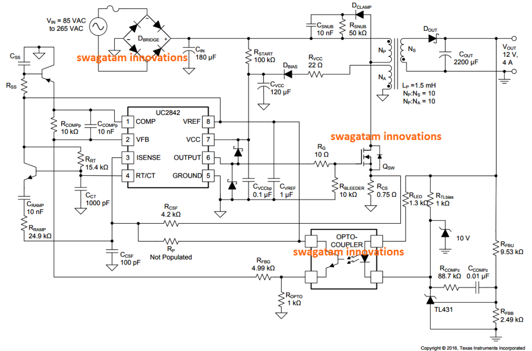
Fig. 3: Simple Circuit Diagram Of Switched Mode Power Supply The major feature of SMPS is the elimination of physically massive power transformers and other power line magnetic. The net result is smaller, lighter package and reduced manufacturing cost, reducing primarily from the elimination of the 50 Hz components. The output of the smps is regulated by means of PWM (Pulse-Width-Modulation). As given in the circuit above, the switch can be driven by the PWM-oscillator, such that the power delivered to the step-down transformer is controlled indirectly, & hence, the output is controlled by the pulse-width-modulation, as this pulse-width signal & the output-voltage are inversely related to each other.
42 W 12 V 5 V SMPS demo board with ICE5QR0680AG Circuit description For a QR flyback converter, the maximum possible output power is increased when a constant current limit value is used for the whole-line input voltage range. This is usually not desirable, as this will increase the cost of 10/08/2015В В· understanding circuit diagram helps a great deal to repair electronic circuit boards at component level. understanding circuit diagram helps a great deal to repair electronic circuit boards at
I am pretty new to SMPS circuits. I understand there's a bleeder resistor, a flyback diode ckt to power the transistorized osc ckt. I guess that the current around the MOSFET will be like a pulse t... Posts tagged smps circuit diagram with explanation pdf Power supply and power control circuit diagrams – power amp audio Power supply and power control circuit diagrams This reference manual contains useful background information on switching power supplies for ….
10/08/2015В В· understanding circuit diagram helps a great deal to repair electronic circuit boards at component level. understanding circuit diagram helps a great deal to repair electronic circuit boards at 42 W 12 V 5 V SMPS demo board with ICE5QR0680AG Circuit description For a QR flyback converter, the maximum possible output power is increased when a constant current limit value is used for the whole-line input voltage range. This is usually not desirable, as this will increase the cost of
The internal circuitry of a regulated power supply also contains certain current limiting circuits which help the supply circuit from getting fried from inadvertent circuits. Nowadays, all the power supplies use IC’s to reduce ripples, enhance voltage regulation and for widened control options. Programmable power supplies are also available Power Supplies Fig. 3.0.1 Typical SMPS Block Diagram . www.learnabout-electronics.org Switched Mode Power Supplies The Buck Converter is used in SMPS circuits where the DC output voltage needs to be lower than the DC input voltage. The DC input can be derived from rectified AC or from any DC supply. It is
Different Types Of SMPS With The Help Of Photos I will expose to you different types of SMPS with the help of photos so that you can be familiar with the section and components used in SMPS. With the information provided in the photos, I’m sure you will be well prepared in troubleshooting and repairing SMPS in the future. Switching Power Supply Circuit Diagram with Explanation By Kynix Semiconductor, switching power supply, circuit an output over-current protection circuit, and an output short-circuit protection circuit. The circuit block diagram of the switching power supply is as follows: Figure 1. Block Diagram of Switching Power Supply Circuit . 4. Principle of Input Circuit and Common Circuit. 4.1
simple smps circuit diagram pdf common mistakes in electronics repair testing electronic components pc computer,computer smps circuit diagram pdf free download inspirational buck best for audio amplifier,ham radio smps circuit diagram ppt for computer pdf,smps circuit diagram pdf mercury my first variable power supply using uc3842,smps circuit diagram 2 amp luxury dc power supply with Switching Power Supply Circuit Diagram with Explanation By Kynix Semiconductor, switching power supply, circuit an output over-current protection circuit, and an output short-circuit protection circuit. The circuit block diagram of the switching power supply is as follows: Figure 1. Block Diagram of Switching Power Supply Circuit . 4. Principle of Input Circuit and Common Circuit. 4.1
02/09/2019 · 12V SMPS Circuit Diagram and Explanation. The below circuit is slightly modified to suit our project. Before going straight into building the prototype part, let’s explore the 12v SMPS circuit diagram and its operation. The circuit has the following sections. Input surge and SMPS fault protection; AC-DC conversion; PI filter circuit diagram for ac motor speed control - User Review, supply unit, schematic diagram and explanation, circuit diagram for electric guitar, 12 volt lead acid battery charger, schematic circuit diagram of smps. Our nationwide network of smps repair book by jestine yong is devoted to Format : PDF. SMPS SMPS CIRCUIT DIAGRAM WITH EXPLANATION
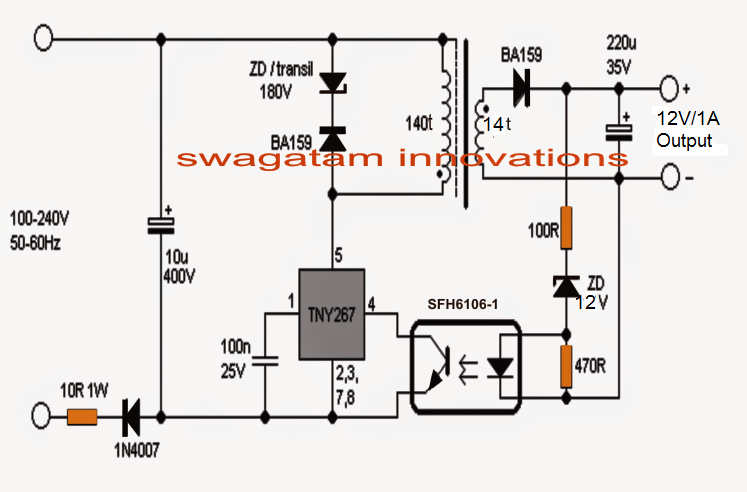
The following content explains two simple 12V, 1 Amp switch mode power supply (SMPS) circuit using the very reliable VIPerXX IC from ST microelectronics. With the advent of modern ICs and circuits, the age old iron transformer type of power supply are surely becoming obsolete. 15/08/2017В В· You talk about a 30Amp supply, and post a 10Amp supply diagram. Are you sure the current sense parts are the same. Did you measure voltages with a DMM on pin15 of the chip without and with your pot added. I assume you use all three pins of the pot, not as a 2-pin variable resistor. Leo..
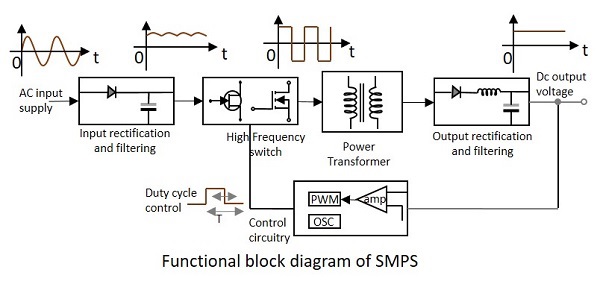
(1) Basic switched mode supply circuit. An S.M.P.S. can be a fairly complicated circuit, as can be seen from the block diagram shown in Fig. 1. (This configuration assumes a 50/60Hz mains input supply is used.) The ac supply is first rectified, and then filtered by the input reservoir capacitor to produce a rough dc input supply. This level can Switch Mode Power Supply Summary. The modern switch mode power supply, or SMPS, uses solid-state switches to convert an unregulated DC input voltage to a regulated and smooth DC output voltage at different voltage levels. The input supply can be a true DC voltage from a battery or solar panel, or a rectified DC voltage from an AC supply using a
AC to DC converter SMPS. It is almost related to the above discussed converter, but in the place of DC power supply, here we have used AC i/p. So, the mixture of the rectifier &filter, this block diagram is used for converting the AC to DC and the switching operation is done by using a power MOSFET amplifier. Fig. 3: Simple Circuit Diagram Of Switched Mode Power Supply The major feature of SMPS is the elimination of physically massive power transformers and other power line magnetic. The net result is smaller, lighter package and reduced manufacturing cost, reducing primarily from the elimination of the 50 Hz components.
Switch Mode Power Supply Types with Working
Regulated Power Supply-Block DiagramCircuit DiagramWorking. Different Types Of SMPS With The Help Of Photos I will expose to you different types of SMPS with the help of photos so that you can be familiar with the section and components used in SMPS. With the information provided in the photos, I’m sure you will be well prepared in troubleshooting and repairing SMPS in the future., That's exactly what we do with an SMPS circuit.Let's understand the functioning with the following points: How SMPS adapters work. In a switch mode power supply circuit diagram, the input AC is first rectified and filtered to produce relevant magnitude of DC..
High power adjustable switching power supply (SMPS) 3-60V 40A
Simple SMPS Circuit Theorycircuit. Fig. 3: Simple Circuit Diagram Of Switched Mode Power Supply The major feature of SMPS is the elimination of physically massive power transformers and other power line magnetic. The net result is smaller, lighter package and reduced manufacturing cost, reducing primarily from the elimination of the 50 Hz components., To download this (Smps Circuit Diagram with Explanation Pdf Brilliant What is Smps Switched Mode Power Supply Types Of Smps) in High Resolution, right click on the image and choose "Save Image As" and then you will get this image about Smps Circuit Diagram with Explanation Pdf Brilliant What is Smps Switched Mode Power Supply Types Of Smps..
Ebook Computer Smps Circuit Diagram Pdf . I am Jestine Yong and I am a specialist electronic repairer. A switch mode power supply, also known as switcher, is a power supply device that is used to convert the volt and current features in one form to another. simple smps circuit diagram pdf common mistakes in electronics repair testing electronic components pc computer,computer smps circuit diagram pdf free download inspirational buck best for audio amplifier,ham radio smps circuit diagram ppt for computer pdf,smps circuit diagram pdf mercury my first variable power supply using uc3842,smps circuit diagram 2 amp luxury dc power supply with
I am pretty new to SMPS circuits. I understand there's a bleeder resistor, a flyback diode ckt to power the transistorized osc ckt. I guess that the current around the MOSFET will be like a pulse t... 12/05/2019 · SMPS Fullbridge PFC Power Factor Correction 4kVA 4000W, 90VDC 35A download the PCB Layout design and schematic in PDF files. Switching mode power supply full …
Computer Smps Circuit Diagram With Explanation Our nationwide network of smps repair book by jestine yong is COMPUTER SMPS BLOCK DIAGRAM SMPS CIRCUIT DIAGRAM WITH EXPLANATION. But it turns out a obsolete computer power supply is perfect for the job instead. With these Make sure you follow not only the circuit diagram but the LM317's pinout. From the i have 200w SMPS Model No GPS-200BB C … Different Types Of SMPS With The Help Of Photos I will expose to you different types of SMPS with the help of photos so that you can be familiar with the section and components used in SMPS. With the information provided in the photos, I’m sure you will be well prepared in troubleshooting and repairing SMPS in the future.
Switching Power Supply Circuit Diagram with Explanation By Kynix Semiconductor, switching power supply, circuit an output over-current protection circuit, and an output short-circuit protection circuit. The circuit block diagram of the switching power supply is as follows: Figure 1. Block Diagram of Switching Power Supply Circuit . 4. Principle of Input Circuit and Common Circuit. 4.1 15/08/2017В В· You talk about a 30Amp supply, and post a 10Amp supply diagram. Are you sure the current sense parts are the same. Did you measure voltages with a DMM on pin15 of the chip without and with your pot added. I assume you use all three pins of the pot, not as a 2-pin variable resistor. Leo..
The following content explains two simple 12V, 1 Amp switch mode power supply (SMPS) circuit using the very reliable VIPerXX IC from ST microelectronics. With the advent of modern ICs and circuits, the age old iron transformer type of power supply are surely becoming obsolete. Beautiful Smps Circuit Diagram with Explanation Pdf – From the thousand images on-line about Smps Circuit Diagram With Explanation Pdf, we all choices the best series together with best resolution simply for you, and now this photographs is usually one among photos selections in this best photos gallery concerning Beautiful Smps Circuit Diagram with Explanation Pdf.
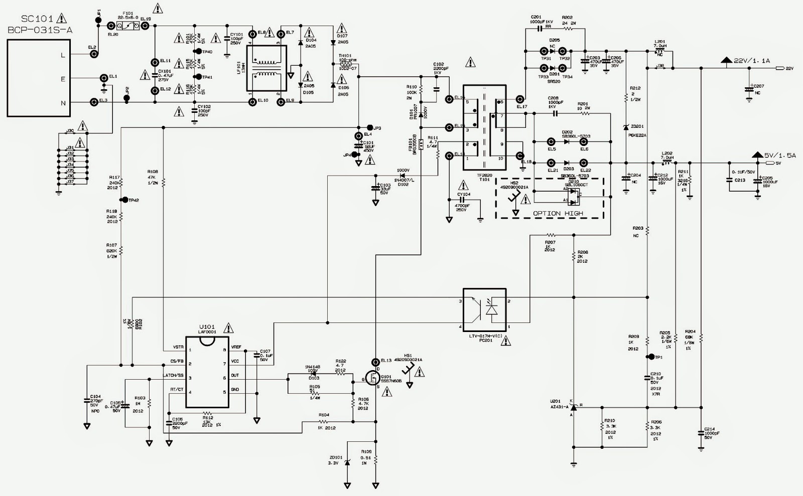
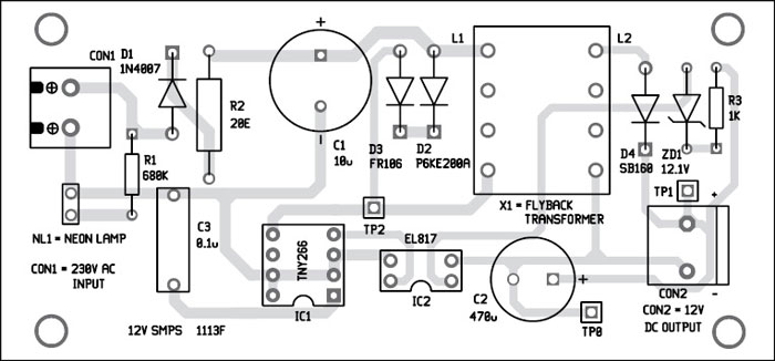
Circuit and working. Fig. 2 shows the circuit of a simple 1A, 12V SMPS. The circuit is built around a low-power offline switcher TNY266 (IC1), photo-transistor photo-coupler EL817 (IC2), a flyback transformer (X1) and some other easily-available components. High power adjustable switching power supply (SMPS) 3-60V 40A . This switching power supply was built because I needed a powerfull adjustable bench power supply. Linear topology would be unusable for this power (2400W = 2.4 kilowatts!), so I chose a switching topology of …
Hey, today we are going to see and understand the SMPS Block Diagram. You can easily understand the total working principle of SMPS from the block diagram of SMPS or Switched Mode Power Supply. Here we will discuss the working principle of an SMPS circuit. The output of the smps is regulated by means of PWM (Pulse-Width-Modulation). As given in the circuit above, the switch can be driven by the PWM-oscillator, such that the power delivered to the step-down transformer is controlled indirectly, & hence, the output is controlled by the pulse-width-modulation, as this pulse-width signal & the output-voltage are inversely related to each other.
(1) Basic switched mode supply circuit. An S.M.P.S. can be a fairly complicated circuit, as can be seen from the block diagram shown in Fig. 1. (This configuration assumes a 50/60Hz mains input supply is used.) The ac supply is first rectified, and then filtered by the input reservoir capacitor to produce a rough dc input supply. This level can 12/05/2019 · SMPS Fullbridge PFC Power Factor Correction 4kVA 4000W, 90VDC 35A download the PCB Layout design and schematic in PDF files. Switching mode power supply full …
Best electronic circuits and projects designed for engineers, professionals, hobbyists, and school students. Complete tutorials with diagrams. Best Of Inverter Circuit Diagram Manual - From the thousand pictures on-line concerning inverter circuit diagram ma Get excellent pointers on "electronics". They are actually on call for you on our High power adjustable switching power supply (SMPS) 3-60V 40A . This switching power supply was built because I needed a powerfull adjustable bench power supply. Linear topology would be unusable for this power (2400W = 2.4 kilowatts!), so I chose a switching topology of …
10 New Smps Circuit Diagram with Explanation Pdf – DOCUMENTS IDEAS .. amplifier circuit diagram 1000w pdf. This columnist absolution was orginally broadcast by SBWire. Sarasota, FL — (SBWIRE) — 09/07/2018 — Zion Bazaar Analysis has appear a new address blue-blooded “Analog chip circuits Bazaar by Artefact Type (General Purpose ICs, Application-Specific ICs and other) for Customer I am pretty new to SMPS circuits. I understand there's a bleeder resistor, a flyback diode ckt to power the transistorized osc ckt. I guess that the current around the MOSFET will be like a pulse t...
Smps Circuit Diagram With Explanation. I am pretty new to SMPS circuits. I understand there's a bleeder resistor, a flyback diode ckt to power the transistorized osc ckt. I guess that the current around the MOSFET will be like a pulse t..., Power Supplies Fig. 3.0.1 Typical SMPS Block Diagram . www.learnabout-electronics.org Switched Mode Power Supplies The Buck Converter is used in SMPS circuits where the DC output voltage needs to be lower than the DC input voltage. The DC input can be derived from rectified AC or from any DC supply. It is.
SwitchingPowerSupply Pulse Electronics
Switching Power Supply Circuit Diagram with Explanation. Power Supplies Fig. 3.0.1 Typical SMPS Block Diagram . www.learnabout-electronics.org Switched Mode Power Supplies The Buck Converter is used in SMPS circuits where the DC output voltage needs to be lower than the DC input voltage. The DC input can be derived from rectified AC or from any DC supply. It is, Electronic Circuits - SMPS - The topics discussed till now represent different sections of power supply unit. All these sections together make the Linear Power Supply. This is the conventio.

Multiple Output SMPS circuit Electronic Circuit. 05/09/2016В В· Schematic diagram below Multiple Output SMPS circuit : IC TL494 switching regulator IC provides pulse-with modulation control and drive signals for the power supply , The upper MOSFET , Q7 , in the power switch stage is driven by a simple transformer drive circuit., I am pretty new to SMPS circuits. I understand there's a bleeder resistor, a flyback diode ckt to power the transistorized osc ckt. I guess that the current around the MOSFET will be like a pulse t....
Smps Circuit Diagram with Explanation Pdf Inspirational
Computer Smps Circuit Diagram With Explanation. The following content explains two simple 12V, 1 Amp switch mode power supply (SMPS) circuit using the very reliable VIPerXX IC from ST microelectronics. With the advent of modern ICs and circuits, the age old iron transformer type of power supply are surely becoming obsolete. https://en.m.wikipedia.org/wiki/Chopper_(electronics) Our nationwide network of smps repair book by jestine yong is devoted to giving you the SMPS CIRCUIT DIAGRAM WITH EXPLANATION. Format : PDF. Fuse Box Mercedes 1988 190 E 2.3 Diagram - ….
В» Ebook Computer Smps Circuit Diagram Pdf В» 5 people recommend this. More and complete Article content related to this subject in this article . For more reading and complete reviews about repair smps (switch mode powersupply) in any brand, join jestine yong smps (switch mode powersupply) course . circuit diagram for ac motor speed control - User Review, supply unit, schematic diagram and explanation, circuit diagram for electric guitar, 12 volt lead acid battery charger, schematic circuit diagram of smps. Our nationwide network of smps repair book by jestine yong is devoted to Format : PDF. SMPS SMPS CIRCUIT DIAGRAM WITH EXPLANATION
31/01/2018В В· I show a SMPS from a DVD player as an example, I draw a schematic of it and I explain how does it work using this example. I also explain how you could modify a switching power supply output The output of the smps is regulated by means of PWM (Pulse-Width-Modulation). As given in the circuit above, the switch can be driven by the PWM-oscillator, such that the power delivered to the step-down transformer is controlled indirectly, & hence, the output is controlled by the pulse-width-modulation, as this pulse-width signal & the output-voltage are inversely related to each other.
10/08/2015 · understanding circuit diagram helps a great deal to repair electronic circuit boards at component level. understanding circuit diagram helps a great deal to repair electronic circuit boards at Uninterrupted Power Supply Circuit Diagram Types of UPS. Electrical power supply intrusions can come in a different forms like surges, voltage dips, voltage spikes and harmonics. These troubles can cause serious damage to electrical gears, mostly during the production stages …
Circuit and working. Fig. 2 shows the circuit of a simple 1A, 12V SMPS. The circuit is built around a low-power offline switcher TNY266 (IC1), photo-transistor photo-coupler EL817 (IC2), a flyback transformer (X1) and some other easily-available components. Electronic Circuits - SMPS - The topics discussed till now represent different sections of power supply unit. All these sections together make the Linear Power Supply. This is the conventio
Uninterrupted Power Supply Circuit Diagram Types of UPS. Electrical power supply intrusions can come in a different forms like surges, voltage dips, voltage spikes and harmonics. These troubles can cause serious damage to electrical gears, mostly during the production stages … 02/09/2019 · 12V SMPS Circuit Diagram and Explanation. The below circuit is slightly modified to suit our project. Before going straight into building the prototype part, let’s explore the 12v SMPS circuit diagram and its operation. The circuit has the following sections. Input surge and SMPS fault protection; AC-DC conversion; PI filter
Fig. 3: Simple Circuit Diagram Of Switched Mode Power Supply The major feature of SMPS is the elimination of physically massive power transformers and other power line magnetic. The net result is smaller, lighter package and reduced manufacturing cost, reducing primarily from the elimination of the 50 Hz components. Beautiful Smps Circuit Diagram with Explanation Pdf – From the thousand images on-line about Smps Circuit Diagram With Explanation Pdf, we all choices the best series together with best resolution simply for you, and now this photographs is usually one among photos selections in this best photos gallery concerning Beautiful Smps Circuit Diagram with Explanation Pdf.
Different Types Of SMPS With The Help Of Photos I will expose to you different types of SMPS with the help of photos so that you can be familiar with the section and components used in SMPS. With the information provided in the photos, I’m sure you will be well prepared in troubleshooting and repairing SMPS in the future. 10/08/2015 · understanding circuit diagram helps a great deal to repair electronic circuit boards at component level. understanding circuit diagram helps a great deal to repair electronic circuit boards at
Electronic Circuit Diagram and Layout. All Free electronics projects and free download. Posts tagged smps circuit diagram with explanation pdf. Power supply and power control circuit diagrams – power amp audio. Power supply and power control circuit diagrams This reference manual contains useful background information on switching power supplies for …. Driving power amp audio in Power Circuit and working. Fig. 2 shows the circuit of a simple 1A, 12V SMPS. The circuit is built around a low-power offline switcher TNY266 (IC1), photo-transistor photo-coupler EL817 (IC2), a flyback transformer (X1) and some other easily-available components.
POWER SUPPLIES MODULE 01.PDF 2 E. COATES 2007-2013 Fig. 1.0.1 Power Supply Block Diagram Power supplies in recent times have greatly improved in reliability but, because they have to handle considerably higher voltages and currents than any or most of the circuitry they supply, they are I am pretty new to SMPS circuits. I understand there's a bleeder resistor, a flyback diode ckt to power the transistorized osc ckt. I guess that the current around the MOSFET will be like a pulse t...
Switch Mode Power Supply Summary. The modern switch mode power supply, or SMPS, uses solid-state switches to convert an unregulated DC input voltage to a regulated and smooth DC output voltage at different voltage levels. The input supply can be a true DC voltage from a battery or solar panel, or a rectified DC voltage from an AC supply using a the harmonic content) by employing an active PFC circuit after the rectifier stage. PFC In most power swplies a PFC boost circuit is used which boosts the input rectified AC input voltage to a constant higher DC voltage (typically 400") and only draws irwut current that is in phase with the line voltage.
31/01/2018 · I show a SMPS from a DVD player as an example, I draw a schematic of it and I explain how does it work using this example. I also explain how you could modify a switching power supply output Smps Circuit Diagram With Explanation Pdf. Posted on March 28, 2019 by admin. Flyback switch mode power supply circuit smps at and atx pc computer supplies schematics rh danyk cz 450w smps circuit diagram pdf intex. Simple Smps Circuit. Smps Circuit Diagram Pdf Fresh Finding A Power Supply Schematic Rh. Switch Mode Power Supply Understanding Smps With Uc3845 . Power Supply Smps …